RoofViews

Building Science

Thermal Bridging Through Roof Fasteners: Why the Industry Should Take Note

By Elizabeth Grant

November 17, 2023

Flat roof with hot air welded pvc membrane waterproofing for ballasted system

What is going on here?

No, this roof does not have measles, it has a problem with thermal bridging through the roof fasteners holding its components in place, and this problem is not one to be ignored.

As building construction evolves, you'd think these tiny breaches through the insulating layers of the assembly, known as point thermal bridges, would matter less and less. But, as it happens, the reverse is true! The tighter and better-insulated a building, the bigger the difference all of the weak points, in its thermal enclosure, make. A range of codes and standards are beginning to address this problem, though it's important to note that there is often a time lag between development of codes and their widespread adoption.

What Is the Industry Doing About It?

Long in the business of supporting high-performance building enclosures, Phius (Passive House Institute US) provides a Fastener Correction Calculator along with a way to calculate the effect of linear thermal bridges (think shelf angles, lintels, and so on). By contrast, the 2021 International Energy Conservation Code also addresses thermal bridging, but only considers framing materials to be thermal bridges, and actually pointedly ignores the effects of point loads like fasteners in its definition of continuous insulation: "insulation material that is continuous across all structural members without thermal bridges other than fasteners and service openings" (Section C202). Likewise, The National Energy Code of Canada for Buildings: 2020 addresses thermal bridging of a number of building components, but also explicitly excludes fasteners: "in calculating the overall thermal transmittance of assemblies…fasteners need not be taken into account" (Section 3.1.1.7.3). Admittedly, point thermal bridges are often excluded because it is challenging to assess them with simple simulation tools.

Despite this, researchers have had a hunch for decades that thermal bridging through the multitude of fasteners often used in roofs is in fact significant enough to warrant study. Investigators at the National Bureau of Standards, Oak Ridge National Laboratory, the National Research Council Canada, and consulting firms Morrison Hershfield and Simpson Gumpertz & Heger (SGH), have conducted laboratory and computer simulation studies to analyze the effects of point thermal bridges.

Why Pay Attention Now?

The problem has been made worse in recent years because changes in wind speeds, design wind pressures, and roof zones as dictated by ASCE 7-16 and 7-22 (see blogs by Jim Kirby and Kristin Westover for more insight), mean that fastener patterns are becoming denser in many cases. This means that there is more metal on average, per square foot of roof, than ever before. More metal means that more heat escapes the building in winter and enters the building in summer. By making our buildings more robust against wind uplift to meet updated standards, we are in effect making them less robust against the negative effects of hot and cold weather conditions.

So, how bad is this problem, and what's a roof designer to do about it? A team of researchers at SGH, Virginia Tech, and GAF set out to determine the answer, first by simplifying the problem. Our plan was to develop computer simulations to accurately anticipate the thermal bridging effects of fasteners based on their characteristics and the characteristics of the roof assemblies in which they are used. In other words, we broke the problem down into parts, so we could know how each part affects the problem as a whole. We also wanted to carefully check the assumptions underlying our computer simulation and ensure that our results matched up with what we were finding in the lab. The full paper describing our work was delivered at the 2023 IIBEC Convention and Trade Show, but here are the high points, starting with how we set up the study.

First, we began with a simple 4" polyisocyanurate board (ISO), and called it Case A-I.

Next, we added a high-density polyisocyanurate cover board (HD ISO), and called that Case A-II.

Third, we added galvanized steel deck to the 4" polyiso, and called that Case A-III.

Finally, we created the whole sandwich: HD ISO and ISO over steel deck, which was Case A-IV.

Note that we did not include a roof membrane, substrate board, air barrier, or vapor retarder in these assemblies, partly to keep it simple, and partly because these components don't typically add much insulation value to a roof assembly.

The cases can be considered base cases, as they do not yet contain a fastener. We needed to simulate and physically test these, so we could understand the effect that fasteners have when added to them.

We also ran a set of samples, B-I through B-IV, that corresponded with cases A-I through A-IV above, but had one #12 fastener, 6" long, in the center of the 2' x 2' assembly, with a 3" diameter insulation plate. These are depicted below. The fastener penetrated the ISO and steel deck, but not the HD ISO.

One visualization of the computer simulation is shown here, for Case B-IV. The stripes of color, or isotherms, show the vulnerability of the assembly at the location of the fastener.

What did we find? The results might surprise you.

First, it's no surprise that the fastener reduced the R-value of the 2' x 2' sample of ISO alone by 4.2% in the physical sample, and 3.4% in the computer simulation (Case B-I compared to Case A-I).

When the HD ISO was added (Cases II), R-value fell by 2.2% and 2.7% for the physical experiment and computer simulation, respectively, when the fastener was added. In other words, adding the fastener still caused a drop in R-value, but that drop was considerably less than when no cover board was used. This proved what we suspected, that the HD ISO had an important protective effect against the thermal bridging caused by the fastener.

Next, we found that the steel deck made a big difference as well. In the physical experiment, the air contained in the flutes of the steel deck added to the R-value of the assembly, while the computer simulation did not account for this effect. That's an item that needs to be addressed in the next phase of research. Despite this anomaly, both approaches showed the same thing: steel deck acts like a radiator, exacerbating the effect of the fastener. In the assemblies with just ISO and steel deck (Cases III), adding a fastener resulted in an R-value drop of 11.0% for the physical experiment and 4.6% for the computer simulation compared to the assembly with no fastener.

Finally, the assemblies with all the components (HD ISO, ISO and steel deck, a.k.a. Cases IV) showed again that the HD ISO insulated the fastener and reduced its negative impact on the R-value of the overall assembly. The physical experiment had a 6.1% drop (down from 11% with no cover board!) and the computer simulation a 4.2% drop (down from 4.6% with no cover board) in R-value when the fastener was added.

What Does This Study Tell Us?

The morals of the study just described are these:

  • Roof fasteners have a measurable impact on the R-value of roof insulation.

  • High-density polyisocyanurate cover boards go a long way toward minimizing the thermal impacts of roof fasteners.

  • Steel deck, due to its high conductivity, acts as a radiator, amplifying the thermal bridging effect of fasteners.

What Should We Do About It?

As for figuring out what to do about it, this study and others first need to be extended to the real world, and that means making assumptions about parameters like the siting of the building, the roof fastener densities required, and the roof assembly type.

Several groups have made this leap from looking at point thermal bridges to what they mean for a roof's overall performance. The following example was explored in a paper by Taylor, Willits, Hartwig and Kirby, presented at the RCI, Inc. Building Envelope Technology Symposium in 2018. In that paper, the authors extended computer simulation results from a 2015 paper by Olson, Saldanha, and Hsu to a set of actual roofing scenarios. They found that the installation method has a big impact on the in-service R-value of the roof.

They assumed a 15,000-square-foot roof, fastener patterns and densities based on a wind uplift requirement of 120 pounds per square foot, and a design R-value of R-30. In this example, a traditional mechanically attached roof had an in-service R-value of only R-25, which is a 17% loss compared to the design R-value.

An induction-welded roof was a slight improvement over the mechanically attached assembly, with an in-service value of only R-26.5 (a 12% loss compared to the design R-value).

Adhering instead of fastening the top layer of polyiso resulted in an in-service R-value of R-28.7 (a 4% loss compared to the design R-value).

Finally, in their study, an HD polyiso board was used as a mechanically fastened substrate board on top of the steel deck, allowing both layers of continuous polyiso insulation and the roof membrane to be adhered. Doing so resulted in an in-service R-value of R-29.5, representing only a 1.5% loss compared to the design R-value.

To operationalize these findings in your own roofing design projects, consider the following approaches:

  • Consider eliminating roof fasteners altogether, or burying them beneath one or more layers of insulation. Multiple studies have shown that placing fastener heads and plates beneath a cover board, or, better yet, beneath one or two layers of staggered insulation, such as GAF's EnergyGuard™ Polyiso Insulation, can dampen the thermal bridging effects of fasteners. Adhering all or some of the layers of a roof assembly minimizes unwanted thermal outcomes.

  • Consider using an insulating cover board, such as GAF's EnergyGuard™ HD or EnergyGuard™ HD Plus Polyiso cover board. Installing an adhered cover board in general is good roofing practice for a host of reasons: they provide enhanced longevity and system performance by protecting roof membranes and insulation from hail damage; they allow for enhanced wind uplift and improved aesthetics; and they offer additional R-value and mitigate thermal bridging as shown in our recent study.

  • Consider using an induction-welded system that minimizes the number of total roof fasteners by dictating an even spacing of insulation fasteners. The special plates of these fasteners are then welded to the underside of the roof membrane using an induction heat tool. This process eliminates the need for additional membrane fasteners.

  • Consider beefing up the R-value of the roof insulation. If fasteners diminish the actual thermal performance of roof insulation, building owners are not getting the benefit of the design R-value. Extra insulation beyond the code minimum can be specified to make up the difference.

Where Do We Go From Here?

Some work remains to be done before we have a computer simulation that more closely aligns with physical experiments on identical assemblies. But, the two methods in our recent study aligned within a range of 0.8 to 6.7%, which indicates that we are making progress. With ever-better modeling methods, designers should soon be able to predict the impact of fasteners rather than ignoring it and hoping for the best.

Once we, as a roofing industry, have these detailed computer simulation tools in place, we can include the findings from these tools in codes and standards. These can be used by those who don't have the time or resources to model roof assemblies using a lab or sophisticated modeling software. With easy-to-use resources quantifying thermal bridging through roof fasteners, roof designers will no longer be putting building owners at risk of wasting energy, or, even worse, of experiencing condensation problems due to under-insulated roof assemblies. Designers will have a much better picture of exactly what the building owner is getting when they specify a roof that includes fasteners, and which of the measures detailed above they might take into consideration to avoid any negative consequences.

This research discussed in this blog was conducted with a grant from the RCI-IIBEC Foundation and was presented at IIBEC's 2023 Annual Trade Show and Convention in Houston on March 6. Contact IIBEC at https://iibec.org/ or GAF at BuildingScience@GAF.com for more information.

About the Author

Elizabeth Grant is the Building & Roofing Science Research Lead at GAF. In this role, she supports GAF’s efforts within the commercial roofing community through engagement with architects and specifiers, providing technical advice and research-based guidance in their design and specification processes. Before joining GAF, she was an associate professor at Virginia Tech’s School of Architecture + Design, publishing papers, conducting studies, and offering courses in architectural design, environmental design research, and environmental building systems. Her architectural experience includes designing healthcare, civic, and educational buildings, and her work focuses on the building enclosure and finding sustainable solutions to pressing architectural and environmental problems.

Related Articles

very severe hail
Building Science

Defending Against Very Severe Hail

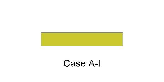
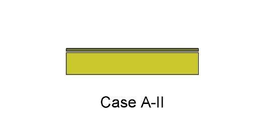
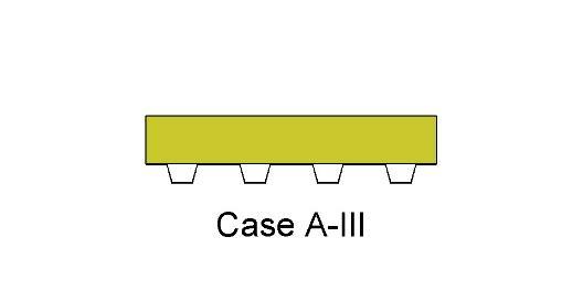
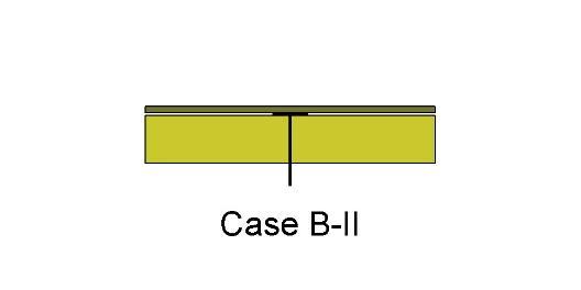
Think that your roof doesn't need protection against hail? Think again.Severe hail events are increasing in geographic footprint and are no longer just in hail alley. The geographic region that experiences 1 inch or larger hailstones has expanded to be nearly two-thirds of the United States. Nearly 10 percent more U.S. properties, more than 6.8 million, were affected by hail in 2021 than in 2020. Coinciding with the increase in properties affected by a damaging hail event in 2021, there was also an increase in insurance claims, which rose to $16.5 billion from $14.2 billion in 2020.Figure 1: The estimated number of properties affected by one or more damaging hail events. Source: NOAA, graphed by VeriskAccording to data from Factory Mutual Insurance Company (FM Global), a leader in establishing best practices to protect buildings, the review of client losses between 2016-20, showed that the average wind/hail losses averaged $931,000 per event. That's a significant impact on a business, and it doesn't account for the other effects that a disruptive loss could have such as headaches from the process of repairing or replacing damaged roofs. As a result, designing the roof to withstand damage from hail events has become not only a best practice, but a necessity.Why does hail size matter?FM Approvals is a third-party testing and certification laboratory with a focus on testing products for property loss prevention using rigorous standards. FM Global, through the loss prevention data sheets, requires the use of FM Approved roof systems. FM Global estimates their clients lose about $130M each year on average from hail events in the United States. Given the increasing volume of severe hail events and the resulting property loss, damage, and financial impacts, FM Global added to the requirements in the FM Loss Prevention Data Sheet (LPDS) 1-34 Hail Damage in 2018. Loss Prevention Data Sheets provide FM's best advice for new construction and for Data Sheet 1-34, this includes new or reroofing projects on existing buildings. Data Sheet 1-34 provides guidelines to minimize the potential for hail damage to buildings and roof-mounted equipment. FM Global intends that the data sheets apply to its insured buildings; however, some designers use data sheets as design guidelines for buildings other than those insured by FM Global.FM's LPDS 1-34 identifies the hail hazard areas across the United States: Moderate Hail hazard area, Severe Hail hazard area, and Very Severe Hail (VSH) hazard area which are defined by hail size. Note that the VSH area roughly correlates to Hail Alley. Hail Alley receives more hailstorms, and more severe ones, compared to other parts of the country.Figure 2: FM's LPDS 1-34 map outlining the different hail categories: moderate, severe, and very severe. The Very Severe area is most commonly referred to as "Hail alley".The hail hazard areas are divided by hail size, with the Very Severe hail hazard area being the largest hail size of greater than 2 inches. As a result, roofing assemblies have to meet the most stringent hail testing for designation in the Very Severe hazard area.Figure 3: Description of FM Approval hail regions.Even if you are not in hail alley, or one of the states in FM's Very Severe Hail area, hail larger than 2 inches still has the potential to occur throughout the contiguous United States. The National Oceanic and Atmospheric Administration (NOAA) tracks weather events throughout the United States, including hail. NOAA's hail database includes information such as location, date, and magnitude (size) of the hail stone for each event. A sampling of typical data is provided below; note that several states that are outside of FM's VSH zone, had hail events that would qualify as VSH, where hail stones were recorded to be larger than 2-inches in size.Figure 4: Hail events in states that are outside of the VSH area, but qualify as VSH by size.How Do I Design For Very Severe Hail?In order for a roof assembly to achieve a hail rating, the assembly must pass a hail test. FM Approvals designs the hail tests including a different test for each hail hazard area. Hail testing generally includes the use of steel or ice balls that are dropped or launched at roof assemblies in a laboratory setting. Pass criteria vary by the test, but generally visual damage cannot be present to either the membrane or components below. Roof assemblies that pass each individual hail test are FM approved to be installed in each hail hazard area.There are thousands of FM rated assemblies and it can be difficult to choose just one. To start, it is important to note that selection consists of an entire assembly, however consideration of all roof components including the membrane, coverboard, and attachment method each play an important role in how the assembly defends against hail.Membrane selection is critical for Very Severe Hail prone regions. Thicker roof membranes, as well as higher performance grades that will remain pliable under heat and UV exposure over time and will outperform standard grade materials. Fleeceback membranes also provide an added cushion layer that buffers hail impact.Coverboard selection is a critical component of the roof system design. High compressive strength coverboards are an effective means to enhance the performance of the roof system when exposed to hail events. A coverboard will enhance the roof's long term performance by fortifying the membrane when hail strikes as well as providing a firm surface to help resist damage from typical foot traffic. It will also help the roof insulation below withstand damage from hail. While conventional gypsum coverboards and high-density polyiso coverboards provide excellent protection against foot traffic and smaller hail, they are not effective for VSH. Coverboards for VSH systems were originally limited to plywood or oriented strand board (OSB). The use of plywood and OSB is very labor intensive to install as compared to traditional gypsum coverboards, increasing the cost of the installation. Recently, coverboard manufacturers have developed glass mat roof boards which are a reinforced gypsum core with a heavy-duty coated glass mat facer. Not only do these boards provide protection against 2-inch hail and are an important part of VSH assemblies, they are also a FM Class 1 and UL Class A thermal barrier for fire rated assemblies. These boards are 5/8" thick and are 92-96 pounds per 4'x8' board; about 30 percent heavier compared to plywood yet easier to install as they can be scored and cut like a traditional gypsum board.Consideration of roof attachment method is critical for selection of VSH assemblies. Historically, mechanically attached systems were not able to pass the VSH tests; when an ice ball hit the head of the fastener or plate, the result was a laceration in the membrane. To avoid failures of the membrane at the fasteners and plates, the fasteners were traditionally buried in the system; the insulation was mechanically attached and the coverboard and membrane were adhered. This is still a common installation method and as a result, there are a large number of assemblies where the membrane and coverboard are adhered. Additionally, burying the fasteners allows for the installation of a smooth backed membrane. With the development of glass mat coverboards, there are VSH rated assemblies that can be simultaneously fastened (mechanically attached coverboard and insulation) that utilize an adhered fleece-back membrane.Figure 5: VSH systems. Left is simultaneously fastened 60 mil Fleeceback TPO over glass mat VSH roof board and Polyiso Insulation. Right is 60 mil Fleeceback TPO over glass mat VSH roof board adhered in low rise foam ribbons to mechanically attached Polyiso Insulation.Figure 6: A sample of available VSH assemblies.SummaryWhy Should We Design for VSH?Severe hail events are increasing in geographic footprint and storms with hailstones that meet Very Severe Hail criteria are occurring throughout the country. While designing for VSH is a requirement if a building falls within the VSH area and is ensured by FM Global, many owners and designers are opting for roof assemblies that can withstand VSH storms even if they are not insured by FM Global. Material selection, such as coverboard and membrane, are key components to managing this risk. Glass mat coverboards and thicker, higher grade single-ply membranes, such as fleece-back, increase the roof assembly's resistance to damage. Choosing the right roof assembly could be the difference between weathering the storm or significant damage from hail.What are the next steps?Learn about GAF's Hail Storm System Resources, and as always, feel free to reach out to the Building & Roofing Science team with questions.

By Authors Kristin Westover

January 30, 2023

Roof design services team
Building Science

How Architects Can Lean on Roof Design Services for Project Success

Architects strive to achieve a roof design that will perform well and meet project-specific requirements. That often means incorporating the building code and warranty/guarantee requirements that building owners must meet — among the most important factors of any construction project — into the design. This isn't made any easier by the sheer number of roofing systems available. Even experienced architects can find it challenging to get familiar with all available components and identify which materials are going to be suitable for a particular building.Enter the GAF Design Services Team. Formed by merging together three different departments — field services, technical support services, and architectural information services — these technical professionals help support architects in delivering high-performing roofing systems that meet project-specific requirements.Support from Start to FinishAs GAF Senior Design Services Specialist Jesse Caruso explains, "The goal of Design Services is to essentially combine all three of those tasks into one large service team that assists architects, engineers, specifiers, consultants, sales reps, and contractors achieve their roof design goals. From the moment someone says they need a new roof, we are there throughout the entire process to provide support, all the way until the end of that roof guarantee."Each region of the country has dedicated Design Services personnel just a phone call away, ready to provide information about GAF commercial roofing systems. They understand the unique needs of different geographic areas of the country."We help walk a contractor or an owner or architect through that entire roofing lifecycle," says Caruso. "From how to install the system to what kind of warranty or guarantee you're going to get and how to maintain that guarantee or warranty."GAF's Port Arthur, TX Design Services Team: Dacia Belt, Nathan Vidrine, Shelby Noland, Brittany Castillo, Stephanie Lawrence, Melissa Vaughan, Traci Hicks, Jessica Crabtree, Traci Smith, Melanie Miller, Shelly Benoit, & Brittany SanchezSome of the topics Caruso's team is asked to assist with most frequently include:Product Testing: The Design Services team can confirm and provide documentation that shows which products and systems meet ASTM or UL standards for fire and hail resistance. They can also verify wind uplift ratings and other special approvals, such as Factory Mutual and Miami-Dade approvals.Installation Guidelines: The team can provide data on how different methods of installation can affect roofs' performance and guarantees. For instance, if a building is in a coastal area and needs a higher wind uplift rating, the team can provide guidance on fastening patterns and other installation strategies that will help meet that wind uplift requirement.Guarantee Terms: One of the most important aspects for building owners to consider is the warranty or guarantee protection provided by the roofing manufacturer. The Design Services team can assist by verifying what types of coverage are available and what contractor certifications are necessary to deliver a certain type of warranty or guarantee.Documentation: The team can provide professional documentation that supports product testing, ratings, and warranty/guarantee information. One submittal package may contain design lines, cut specs, system letters, data sheets, and more. This documentation can provide assurance from the manufacturer that the roof system will meet or exceed project requirements.An Architect's Partner for SuccessNo matter what challenges professionals may encounter while designing a new roofing system, the GAF Design Services Team is there to assist. You can be confident that the finished roofing system will provide the desired performance and protect the building for years to come.Reach out to the team by emailing designservices@gaf.com or visiting the design professionals help page.

By Authors Karen L Edwards

November 22, 2022

Rolling out cooling GAF Streetbond® coating in blue and white, Pacoima, L.A.
In Your Community

Creating Net-Positive Communities: GAF Taking Action to Drive Carbon Reduction

Companies, organizations, and firms working in the building, construction, and design space have a unique opportunity and responsibility. Collectively, we are contributing to nearly 40% of energy-related carbon emissions worldwide. While the goals, commitments, pledges, and promises around these challenges are a step in the right direction, no one entity alone will make major improvements to this daunting issue.We need to come together, demonstrate courageous change leadership, and take collective approaches to address the built environment's impacts on climate. Collectively, we have a unique opportunity to improve people's lives and make positive, measurable changes to impact:Buildings, homes, and hardscapesCommunity planningConsumer, commercial, and public sector behaviorOur Collective Challenge to Reduce our Carbon FootprintAccording to many sources, including the U.S. Green Building Council (USGBC), the built environment accounts for 39% of global energy-related carbon emissions worldwide. Operational emissions from buildings make up 28% and the remaining 11% comes from materials and construction.By definition, embodied carbon is emitted by the manufacture, transport, and installation of construction materials, and operational carbon typically results from heating, cooling, electrical use, and waste disposal of a building. Embodied carbon emissions are set during construction. This 11% of carbon attributed to the building materials and construction sector is something each company could impact individually based on manufacturing processes and material selection.The more significant 28% of carbon emissions from the built environment is produced through the daily operations of buildings. This is a dynamic that no company can influence alone. Improving the energy performance of existing and new buildings is a must, as it accounts for between 60–80% of greenhouse gas emissions from the building and construction sector. Improving energy sources for buildings, and increasing energy efficiency in the buildings' envelope and operating systems are all necessary for future carbon and economic performance.Why It Is Imperative to Reduce our Carbon Emissions TodayThere are numerous collectives that are driving awareness, understanding, and action at the governmental and organizational levels, largely inspired by the Paris Agreement enacted at the United Nations Climate Change Conference of Parties (COP21) in 2015. The Architecture 2030 Challenge was inspired by the Paris Agreement and seeks to reduce climate impacts from carbon in the built environment.Since the enactment of the Paris Agreement and Architecture 2030 Challenge, myopic approaches to addressing carbon have prevailed, including the rampant net-zero carbon goals for individual companies, firms, and building projects. Though these efforts are admirable, many lack real roadmaps to achieve these goals. In light of this, the US Security and Exchange Commission has issued requirements for companies, firms, and others to divulge plans to meet these lofty goals and ultimately report to the government on progress in reaching targets. These individual actions will only take us so far.Additionally, the regulatory environment continues to evolve and drive change. If we consider the legislative activity in Europe, which frequently leads the way for the rest of the world, we can all expect carbon taxes to become the standard. There are currently 15 proposed bills that would implement a price on carbon dioxide emissions. Several states have introduced carbon pricing schemes that cover emissions within their territory, including California, Oregon, Washington, Hawaii, Pennsylvania, and Massachusetts. Currently, these schemes primarily rely on cap and trade programs within the power sector. It is not a matter of if but when carbon taxes will become a reality in the US.Theory of ChangeClimate issues are immediate and immense. Our industry is so interdependent that we can't have one sector delivering amazing results while another is idle. Making changes and improvements requires an effort bigger than any one organization could manage. Working together, we can share resources and ideas in new ways. We can create advantages and efficiencies in shared R&D, supply chain, manufacturing, transportation, design, installation, and more.Collaboration will bring measurable near-term positive change that would enable buildings and homes to become net-positive beacons for their surrounding communities. We can create a network where each building/home has a positive multiplier effect. The network is then compounded by linking to other elements that contribute to a community's overall carbon footprint.Proof of Concept: GAF Cool Community ProjectAn estimated 85% of Americans, around 280 million people, live in metropolitan areas. As the climate continues to change, many urban areas are experiencing extreme heat or a "heat island effect." Not only is excess heat uncomfortable, but heat islands are public health and economic concerns, especially for vulnerable communities that are often most impacted.Pacoima, a neighborhood in Los Angeles, was selected by a consortium of partners as a key community to develop a first-of-its-kind community-wide research initiative to understand the impacts various cooling solutions have on urban heat and livability. Pacoima is a lower income community in one of the hottest areas in the greater Los Angeles area. The neighborhood represents other communities that are disproportionately impacted by climate change and often underinvested in.Implementation:Phase 1: This included the application of GAF StreetBond® DuraShield cool, solar-reflective pavement coatings on all ground-level hard surfaces, including neighborhood streets, crosswalks, basketball courts, parking lots, and playgrounds. The project also includes a robust community engagement process to support local involvement in the project, measure qualitative and quantitative impact on how cooling improves living conditions, and ensure the success of the project.Phase 2: After 12 months of monitoring and research, GAF and partners will evaluate the impact of the cool pavements with the intent to scale the plan to include reflective roofing and solar solutions.This ongoing project will allow us to evaluate for proof of concept and assess a variety of solutions as well as how different interventions can work together effectively (i.e., increasing tree canopies, greenspacing, cool pavements, cool roofs, etc.). Through community-wide approaches such as this, it's possible that we could get ahead of the legislation and make significant innovative contributions to communities locally, nationally, and globally.GAF Is Taking Action to Create Community-wide Climate SolutionsWith collaboration from leaders across the building space and adjacent sectors, we believe it is possible to drive a priority shift from net neutral to net positive. Addressing both embodied and operational carbon can help build real-world, net-positive communities.We invite all who are able and interested in working together in the following ways:Join a consortium of individuals, organizations, and companies to identify and develop opportunities and solutions for collective action in the built environment. The group will answer questions about how to improve the carbon impacts of the existing and future built environment through scalable, practical, and nimble approaches. Solutions could range from unique design concepts to materials, applications, testing, and measurement so we can operationalize solutions across the built environment.Help to scale the Cool Community project that was started in Pacoima. This can be done by joining in with a collaborative and collective approach to climate adaptation for Phase 2 in Pacoima and other cities around the country where similar work is beginning.Collaborate in designing and building scientific approaches to determine effective carbon avoidance—or reduction—efforts that are scalable to create net-positive carbon communities. Explore efforts to use climate adaptation and community cooling approaches (i.e., design solutions, roofing and pavement solutions, improved building envelope technologies, green spacing, tree coverage, and shading opportunities) to increase albedo of hard surfaces. Improve energy efficiency to existing buildings and homes and ultimately reduce carbon at the community level.To learn more and to engage in any of these efforts, please reach out to us at sustainability@gaf.com.

By Authors Jennifer Keegan

September 07, 2022

Don't miss another GAF RoofViews post!

Subscribe now