Thermal insulation is an important part of commercial roofing assemblies. As with anything, there are ways to design with and install polyiso insulation — a better way, a best way, and many variations in-between! Ce qui peut être le mieux pour réduire les coûts initiaux peut s'avérer seulement bon ou très mauvais sur la durée de vie à long terme du bâtiment.
As discussed later, important points to remember about polyiso and its use include:
- Due to polyiso's very low air permeability, good design and installation practices can result in low risks of condensation, even for buildings with somewhat higher than normal humidity levels.
- Building designers can use the label R-value, stated at a mean temperature of 75°F, for projects in most ASHRAE climate zones. However, for climate zones 6 and 7, it may be appropriate to use published values at 40°F.
- Electricity is four times as expensive as gas, on an equivalent Btu basis. Therefore, polyiso's greatest value is seen during summer months when air conditioning usage is at its highest.
Introduction
Polyiso has become the go-to insulation for commercial roofing with about 75 % market share. The reasons include:
- Lowest cost per R-value.
- High R-value per inch, meaning it doesn't require as much thickness as other types of rigid insulation to achieve the same insulation performance.
- Good fire resistance. Being a thermoset unlike polystyrene foams, it doesn't melt during a fire. Melting of thermoplastic foams and subsequent flowing down of molten material through the deck into a building can be hazardous for occupants and fire crews.
- Solvent compatibility - adhesives used in adhered systems don't adversely affect polyiso. This is not the case with polystyrene foams.
- Reduced condensation — When installed correctly in a properly designed system, polyiso helps to resist interior air from reaching the underside of the membrane, thereby reducing condensation risks.
However, just because polyiso is specified and used doesn't mean that the ideal outcome is reached. There are installation details that need to be considered.
Single-ply membrane combined with polyiso can make for a good roof, but additional factors can improve performance:
The Basics
Polyiso boards have straight cut edges (the boards are not tongue and grooved). These butt joints between boards can allow for vertical air movement.
Polyiso was often installed as a single layer:

As shown in the figure above, a single layer of butt-jointed insulation is generally a bad idea and is no longer allowed by the International Building Code (IBC) in the 2018 and newer versions. For roofs with a single layer of butt-jointed insulation boards:
- There is little restriction for air flow and so, during wind events, wind uplift forces result in membrane billowing for attached systems.
- Membrane billowing draws interior conditioned air up to the underside of the membrane and may create a risk of condensation within the assembly.
- Billowing may place additional stress on membrane fasteners, a factor recognized by membrane manufacturers by the issuance of shorter guarantees or warranties for mechanically attached versus adhered membrane.
- Essentially unrestricted air flow up into the assembly diminishes the insulation value and lowers energy efficiency.
In contrast, two layers of polyiso restrict the free flow of air into the roof assembly. Care must be taken to seal between roof penetrations and the polyiso, or air is still free to move up into the assembly as shown here:

Spray foam is a good choice for achieving a seal between the polyiso and the penetrations.
Two layers of polyiso with staggered joints and sealed penetrations is a good system, but two of its features still reduce its insulation efficacy. These are shown in the following magnified view of a roof assembly cross-section.

This cross-section illustrates lower energy efficiency resulting from:
- Insulation and membrane fasteners both act as thermal bridges, conducting heat through the assembly.
- Gaps between insulation boards that allow thermal convection to occur
- When both the insulation and membrane are attached and fastener densities are at their highest, R-value reductions of up to 29 % have been predicted.
Adhered versus Attached
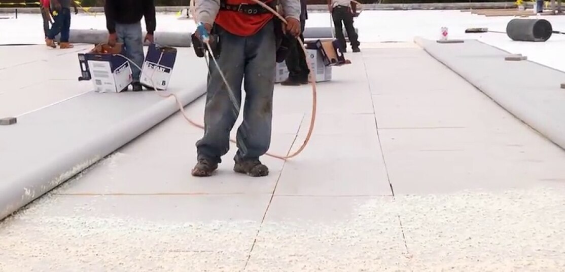
The alternative to mechanical attachment is to adhere the insulation with adhesive. Typically, low rise foam is the adhesive used for both insulation and cover board installation. The original method of application was as a ribbon but for labor savings it is often sprayed in a spatter-pattern as shown in the following picture of a typical installation in progress using one of GAF's low rise foams

Usually, when polyiso is adhered, the roof membrane is also adhered. For a steel deck substrate, fasteners are typically only used for the first layer of insulation, and then the adhesive is used on the subsequent layers of insulation and membrane. While it may be possible to adhere directly to a steel deck and eliminate fasteners totally, this approach is more common with concrete decks, as shown in the schematic here:

Key features of systems with adhered insulation are:
- Air flow up through the assembly is limited and the risk of condensation in cold climates is low. Similarly, membrane billowing is minimized due to the restricted air flow up through adhered insulation layers.
- Thermal bridging is minimized since only the first layer of insulation might be mechanically attached. With concrete decks, the first layer of polyiso can be adhered thereby eliminating the use of fasteners totally.
- Wind uplift resistance is uniformly distributed across the roof deck. A system with adhered membrane and insulation can act as a monolithic system with excellent wind uplift resistance.
- When combined with an adhered membrane the finished roof appearance is usually aesthetically pleasing. When applied in accordance with manufacturer's instructions, the membrane can be very flat and there will not be any insulation fasteners to telegraph through and mar the appearance.
Soudés par induction
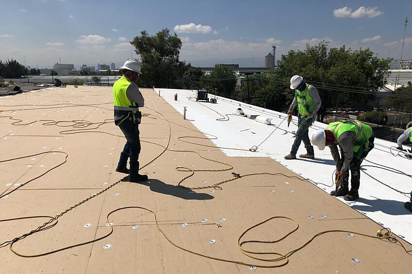
Induction welded fasteners are another type of roof attachment, the largest type being the Drill-Tec™ RhinoBond® system. By definition this is a mechanical attachment method but it has many of the features of adhered systems. The technique fastens TPO and PVC membranes to the substrate below using a microprocessor controlled induction welding machine. The thermoplastic roof membrane is welded directly to specially coated fastening plates used to attach the insulation. The picture below shows such a system being used:

The induction machine is placed above each plate in turn and activated for approximately 10 seconds. As the machine is moved to the next position, a weighted magnet is placed over the plate and acts to squeeze the membrane down onto the hot fastener plate causing it to weld to that plate's surface coating.
For typical mechanical attachment of single-ply membranes with fasteners along the seam lines, the insulation boards are simply secured with five fasteners per 4 x 8 ft. board to keep them flat. When using a Drill-Tec™ RhinoBond® system, the combined insulation and membrane fasteners resist wind uplift forces as shown in this picture during a test of wind uplift resistance:

This means that wind loads are more uniformly distributed versus a conventionally attached system.
Key features of systems with induction welded membrane attachment are:
- Performance is very similar to adhered in terms of the distribution of loads.
- Thermal bridging is reduced compared to traditional mechanically attached membrane systems.
- There are no application temperature restrictions and so this approach can be used in place of adhesive attachment regardless of how cold it might be.
- Drill-Tec™ RhinoBond® systems can be cost competitive due to the speed of installation as compared with traditional bucket and roller adhesives.
Dew Point Calculations
The dew point is the temperature at which moisture vapor forms condensation. It's a function of the relative humidity and the ambient temperature. The evaluation of a roof assembly where the dew point might be reached is an important step towards designing a roof with minimized condensation risks. The topic has been covered in greater depth elsewhere, but this section summarizes the key steps. Examine the chart below (this is a simplified form of what is used by HVAC engineers).

Locating 40 % relative humidity in the first column and then going across to the 70°F, design dry bulb temperature shows a dew point of 45°F. This means that in an environment that is 70°F and 40 % relative humidity (RH), water in the air will condense at a temperature of 45°F. A roof assembly separates the interior conditioned environment from the outside and the insulation layer in the roofing system resists heat loss or gain to/from the outside, depending on the season. Within the insulation layer the temperature has a gradient between the hot and cold side, i.e. between inside and outside.
As an example, consider a building in the winter to illustrate the point. The interior is 70 °F with 40 % RH, like the example on the chart above. The temperature gradually drops from the innermost part of the insulation until at the outermost part it will be at the exterior, cold temperature. The plotting of temperature through the insulation thickness is referred to as the temperature gradient of that system. Using the example, if the temperature gets to the dew point of 45°F at any point in that system then water would be expected to condense on the nearest surface. This is shown in the following diagram:

Summarizing, in this example the interior air has 40 % of the total water vapor that it can support. But as the air migrates up through the roof system, it gets cooler until the point where it can no longer hold onto the water vapor and condensation occurs. In the example shown above, that's at 45°F and just inside the insulation layer.
- As will be discussed later, dew point calculations can be used to inform the placement of a vapor retarder layer when used.
- When a dedicated vapor retarder layer is not used, it is good practice to ensure that the dew point is in the upper layer of polyiso insulation. This will lower the risk of interior air migrating up through the roof assembly and condensing on a surface below its dew point.
Using Vapor Retarders with Polyiso
Vapor retarders can be used to limit humidity ingress to the roof assembly. Under certain circumstances, depending on the building use and location, condensation can occur as discussed in the previous dew point discussion. In general there are four basic building conditions that can be considered:
1. Buildings with Standard Amounts of Occupancy-Generated Moisture
These are the most common situations covering for example, office, retail, and warehouse spaces. The risk of having a condensation issue is low and good roofing practices such as sealing around penetrations may likely suffice.
2. Buildings with Larger Amounts of Occupancy-Generated Moisture
This category includes apartments and other multiple residency buildings, paper mills, laundries, buildings with indoor swimming pools, and the like. In fact, anything that doesn't fit into category 1 above should be evaluated to determine humidity levels. The building's air handling and ventilation systems should be carefully specified to take into account the moisture loading.
3. Construction–Related Moisture
Most construction practices release some amount of moisture into the building space. These can be relatively short term such as drywall installation and painting. However, some practices can release large amounts of water over a considerable time frame into the building. These include poured in place concrete floors and roof decks.
4. Concrete Roof Decks
These can present a challenge for roof system designers especially in new construction. Regardless of the type of concrete, significant amounts of water remain after curing is completed. Allowing concrete to thoroughly dry is most appropriate; however, it is often reasonably impractical. Dealing with potential moisture in concrete decks is beyond the scope of this article, but guidance can be found elsewhere.
It is recommended that a building science professional experienced in designs for Categories 2, 3, and 4 be involved to determine whether a vapor retarder should be used and what type.
Specification of R-Value
Polyiso is manufactured to meet the ASTM C1289 Standard Specification for Faced Rigid Cellular Polyisocyanurate Thermal Insulation Board. ASTM C1289 specifies the thermal resistance at a mean temperature of 75°F for various product thicknesses and requires that the values at 40 and 110°F be made available upon request.
Important features of manufacturer's published R-values are:
- The values are an average across a temperature range. The test methods need the insulation specimen to have a hot and a cold side at least 40°F apart. Most reputable test labs use a difference of 50°F for accuracy. A published value at 75°F is actually an average R-value across the range of 50 to 100°F.
- To take into account the diffusion of gas out of, and air into the polyiso foam, the values are based on projected "Long Term Thermal Resistance" or LTTR, obtained by rapidly aging thin slices of the foam.
- The Polyisocyanurate Insulation Manufacturers Association, PIMA, conducts a third-party certification program to independently validate LTTR values. This is referred to as the PIMA QualityMark™ program. The LTTR values are considered as "labelled R-values" to be used by building design professionals.
- Label R-values represent a 15-year time-weighted average value. They can help a design professional estimate a building's energy efficiency without having to be concerned about long-term loss of performance, which is already factored into the value.
- Building design professionals designing roofs for ASHRAE climate zones 6 and 7 may need to use the R-value reported for a mean temperature of 40°F.
Attachment Patterns
The various fastener patterns for polyiso have been mentioned in the previous sections. However, due to the impact of fasteners on thermal bridging and wind uplift resistance, the key points are summarized here:
- For systems that have both mechanically attached membrane and insulation, the membrane attachment provides the wind uplift resistance. The polyiso insulation fasteners are simply there to hold the insulation flat during the roof installation and to resist long term lateral movement.
- Typical fastener patterns are shown here:

- For systems with adhered single-ply membrane and mechanically attached polyiso boards, the insulation fasteners provide the wind uplift load resistance. This is the case whether both layers of polyiso are mechanically attached or only the bottom layer (in which case the upper layer would be adhered).
- Manufacturers have tested the fasteners per board required to meet wind uplift resistance requirements for these combined mechanically attached and adhered systems. The number of fasteners needed depends on the board size and thickness. For common systems, the numbers are shown in the table below:

- For each of these combinations above, manufacturers' handbooks provide fastener patterns.
- The number of fasteners for these combined mechanically attached and adhered systems is very large, for example a 125 000 s.f. big box type roof could require around 50 000 fasteners, resulting in significant thermal bridging.
- When installing over a steel deck, to reduce thermal bridging and to make for a more robust system with reduced condensation risk, it is advisable to only attach the first layer of polyiso and to adhere all subsequent layers and the membrane.
- If the first layer of polyiso is attached and the rest of the system adhered, then using a 1,5" thickness for that first layer would help to bury the thermal bridging fasteners. It could also put the dividing line between first and second polyiso layers below the dew point, which is advisable.
Pour conclure
- Polyiso is a cost-effective roof insulation and has the advantage that its permeability is low. Good design and installation practices can result in low risks of condensation even for buildings with higher than normal humidity levels.
- When designed correctly, mechanically attached components with two layers of polyiso having staggered and offset joints can be part of a successful roof system.
- Adhered insulation and membrane roof systems have advantages including reduced or eliminated thermal bridging, lowered condensation risks, and better wind uplift resistance.
- In cases where building use anticipates higher interior humidity levels and/or the local climate suggests higher condensation risk, then a building science professional should be consulted as to vapor retarder use and specification.
- Building designers and specifiers are advised to use the labelled R-values shown for a mean temperature of 75°F. For projects in ASHRAE climate zones 5 and 6, values at 40°F could be used depending on the building's geometry and local energy costs.


