RoofViews

Building Science

Roof Design Considerations When Incorporating Solar

By Jennifer Keegan

August 27, 2019

Solar panels

If photovoltaic systems (solar arrays) were installed on all the commercial buildings in the US with roofs over 5,000 sq. ft., they are estimated to provide enough energy to power nearly 60% of the total commercial electricity demand. Commercial rooftops are an appealing option as a platform for installing solar arrays to support energy conservation and generation, as well as corporate and community energy initiatives. However, it is important to remember that the roof's primary function is to protect the building and its contents from the elements.

When considering rooftop solar, the roof system should be designed to have an equivalent or longer lifespan than that of the solar arrays. Whether it's a new roof with solar arrays or will have solar arrays installed in the near future, or it's an existing roof that will receive solar, there are many important considerations for roof system design and panel layout.

Roof System Durability

Solar arrays have a useful economic life of up to 25+ years. For commercial rooftop solar, it is often cost-prohibitive to remove the solar arrays, install a new roof and reinstall the solar arrays. Therefore, the best time to install a rooftop solar system is right after a new roof installation or right after a building is newly constructed. The key issue here is that the roof system should have an expected useful life that matches or exceeds the expected economic life of the solar array. To specify a roof system that is as durable as the solar array, designers should consider the following:

  • Adhered roof membranes with higher heat resistance and greater mil thickness;
  • Incorporation of a cover board;
  • Use of high compressive strength rigid insulation; and
  • Roof system warranty or guarantee that exceeds the life expectancy of the solar arrays

Roof Membranes

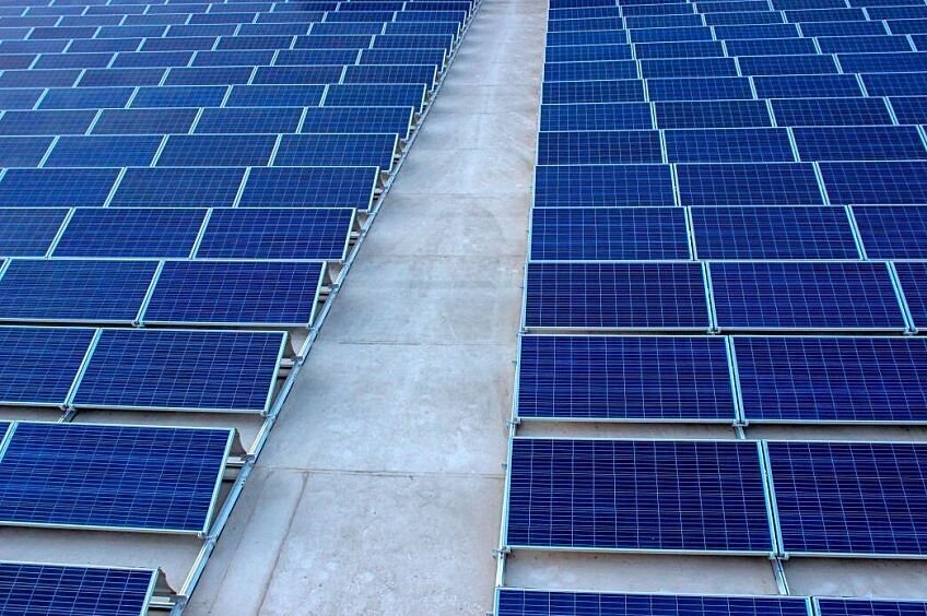
By their nature, reflective roof membranes are beneficial in reducing heat build-up around solar arrays as the temperature of a solar panel can significantly impact how much electricity the panel produces. As panels get hotter, they produce less power. We estimate the efficiency of a solar panel to be up to 13% higher when installed over a highly reflective membrane compared to a dark membrane with low reflectance. Also, the use of bifacial solar panels over reflective roof membranes can increase the efficiency by 20-35%, as they take advantage of the reflected light.

The benefits of specifying a roof membrane that offers enhanced protection against the effects of UV radiation and high service temperatures, and can maintain high reflectance over a long period of time, makes sense when working with rooftop solar. Therefore, regardless of the type of solar installation, the National Roofing Contractors Association (NRCA) recommends the use of a roof membrane that provides enhanced protection against the effects of UV radiation and high service temperatures – for example, GAF's EverGuard Extreme® TPO – to help ensure that the roof life expectancy will match that of the solar arrays.

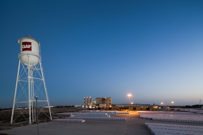
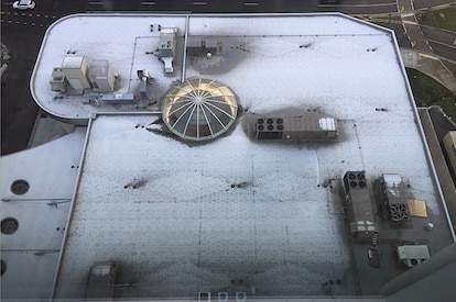
Example of a highly reflective roof membrane (installed on the lower roof) that maintains its reflectivity as it ages.


Designers and owners may also want to consider an increased roof membrane thickness to match the service life of the solar arrays. Using wider rolls will minimize the number of seams and reduce the potential for seams to be obscured below solar arrays.

Membrane Attachment

The membrane attachment method should be carefully considered. Adhering the membrane will avoid the normal billowing of mechanically fastened single ply membranes, which could cause ballasted systems to shift and result in localized abrasion of the membrane. The use of a protection or separation sheet installed between ballasted supports and the membrane, extending beyond the contact surface area on all sides, can protect the membrane from abrasion and may be required for warranty or guarantee coverage. The protection sheet should be secured to the roof membrane, not to the bottom of the racking system.

Ballasted systems inadvertently placed directly over fasteners may cut or puncture the membrane as the solar array shifts during strong wind events. Burying fasteners in the roof system will minimize the potential of damage (photo) to the roof membrane, as well as enhance thermal performance of the roof system. This reinforces the use of adhered membranes as well as an adhered top layer of insulation and cover board.

Adhered arrays attached to a mechanically attached or induction welded roof system will billow and flutter with the roof membrane. Over time, this could create additional stress on the solar arrays and their connections, and may compromise the solar and roof system performance. Therefore, an adhered roof membrane will contribute to a roof system lifespan that will better match that of the solar arrays, and help enhance the performance of both. Of course, it's necessary to verify material compatibility, long-term durability and heat aging capabilities of the adhesive to the roof membrane and solar arrays, as well as compliance with local code and uplift resistance requirements.

For attached or penetrating systems (i.e. non-ballasted), mechanically attached membranes could be more acceptable than with ballasted systems. Attached arrays do not move and the array attachment points might act as additional anchors for the membrane.

Cover Boards and Insulation

Roof durability is system dependent so we must look beyond the membrane and consider the entire roof assembly. Rooftops with solar arrays are burdened with more trades and increased foot traffic on the roof, and therefore, are more susceptible to degradation and potential leak sources. An easy starting point is to protect high traffic areas with walkway pads. The addition of a hard cover board such as HD polyiso board will also enhance system protection and extend the life expectancy of the roof.

In addition to increased foot traffic, concentrated loads from ballasted systems can exceed the compressive strength of the roof system's membrane and insulation. Specifying a rigid insulation board with high compressive strength, such as a Grade 3 polyiso, will distribute loads and help prevent crushing that may occur with lower compressive strength materials.

Installation

As the cost to install solar arrays is significant, performing an integrity test of the roof membrane prior to installing the solar overburden is a worthwhile investment of time and resources. Designers must understand that with the installation of rooftop solar, the roof system becomes a permanent platform for the continuous operation, service, and maintenance of the arrays. As many solar designers are not intimately familiar with best roofing practices, it is helpful to specify solar layout requirements for rooftop access that align with not only code requirements (i.e., International Fire Code, (IFC) and National Electric Code (NFPA 70)), but with best practices for roof maintenance and safety of rooftop workers. This can include requirements such as prohibiting solar arrays from crossing expansion joints, and setting solar arrays and rack heights such that field seams, drains, and penetrations are accessible for emergency responders and maintenance workers.

Designers and owners also have the opportunity to specify the type of solar attachment, which includes attached, ballasted, or adhered. Each option will impact decisions for the roof system design so project teams should take a holistic approach to any value engineering discussions regarding the roof and solar arrays.

The importance of the electrical and solar contractors collaborating in concert with roofing contractors and design professionals cannot be overstated. Qualified roof professionals must be integrally involved through the design process and inspection (and repair as needed) of the roof after solar installation. Specifying this as a requirement will ensure the roof contractor is engaged throughout the entire process, leaving your roof in the proper condition to protect what matters most.

Solar Array Attachment

Designers have many choices when it comes to solar array attachment and not all systems are considered equal. The NRCA recommends the use of attached or penetrating systems, mounting systems that are attached through the roof to the structure. Penetrations and flashings must be well detailed and coordinated with the roofing contractor, solar contractor, and electrician. These details are critical to the success of the installation and must be designed to align with the life expectancy of the solar array and roof system.

Attached Solar


Ballasted Solar


Adhered Solar


While ballasted systems are cost effective and easy to install, they can add up to 5 pounds per square foot to the roof. While this loading can be incorporated into the structural design for new construction, it may exceed the capacity of an existing building. Additionally, the concentrated loading of ballasted systems can exceed the compressive strength of the roof insulation. Therefore, the use of a higher compressive strength insulation such as Grade 3 polyiso, should be strongly considered. Better yet, specify a cover board such as HD polyiso for added protection.

Ballasted systems can shift and flutter during high winds and seismic activity. This can result in surface abrasion of the roof membrane which can be "detrimental to satisfactory long-term roof system performance", according to the NRCA. If the project team accepts the risks associated with ballasted systems, a protection or separation sheet should be installed between the ballast supports and the membrane, and should be secured to the roof membrane, not the ballast supports.

Ballasted trays can block or inhibit drainage, which can result in ponding water on the roof membrane. This can undermine the performance and service life of the roof system. Given all the performance challenges with ballasted systems, "NRCA is of the opinion ballasted rack systems do not satisfy the equivalent service life criteria necessary for successful roof system performance throughout the useful life of rooftop-mounted PV systems." However, as ballasted systems are often used, it is important to understand potential issues and use an appropriate design approach with your roof system so the lifespan of the roof can exceed that of the solar arrays.

Another attachment option for solar arrays includes adhered thin-film panels which are adhesively applied directly to the roof membrane. The low profile application makes this system attractive to many designers. Documented compatibility between the roof membrane and the adhesive is critical. Of utmost concern is the potential for adhered solar panels to detach over time as the adhesive ages, and experiences elevated temperatures and repetitive wind uplift forces.

As previously discussed, adhered solar arrays require an adhered roof membrane. And given the increased heat load on the roof system with adhered arrays, a roof membrane with enhanced heat aging properties is even more critical.

Solar Array Layout

The logic behind the layout of solar arrays applies to all attachment options. Solar arrays are usually oriented and laid out for maximum solar energy collection. This includes keeping panels back from walls or equipment that provides shading and away from hot air exhaust that will impact efficiency. Designers should also consider the appropriateness of solar arrays installed in high-wind zones, such as corners and perimeters, to avoid potential uplift failures of the solar arrays or the roof system. Arrays should also be configured in such a way to avoid additional snow accumulation.

The layout of solar arrays should also address access for solar installation, solar array and roof maintenance, and fire safety. Safe access of the solar contractors and electricians during installation, as well as service and maintenance over the service life of the solar arrays, must be accounted for in the design. This may include davits or other tie-off points, perimeter access, and consideration to proximity of overhead power lines. The NRCA Guidelines conveniently summarize the requirements from the International Fire Code (IFC) and National Electric Code (NFPA 70). Generally, they require a 4-foot perimeter around roof edges, hatches and a pathway between the two, as well as a pathway along both centerline axes. They also recommend a 4-foot wide pathway to skylights, ventilation hatches and roof stacks for future serviceability. Best practices for fire safety include 8-foot wide pathways for smoke ventilation between panel arrays, and getting approval from the local fire chief.

Rooftop solar layout guidelines published in NRCA Guidelines.


Roof system maintenance is also an important consideration for solar array layout. It is important to align solar arrays and set rack heights such that there is enough clearance to service the roof membrane, especially drains and penetrations. Providing additional space between the arrays and the roof membrane also increases ventilation and reduces heat build-up, which results in more efficient panels. Generally, the most efficient solar arrays are installed in conjunction with vegetative roofs, as they provide a better climate and temperature for solar panels to function, which improves electricity production. The relatively small payback period and the environmental benefits of combining these two sustainable approaches can balance out the initial investment.

Solar Roof System Design Summary

Clearly, there is a lot to consider when adding solar arrays to the roof. The good news is that as rooftop solar becomes more popular, there are more resources available to designers, owners and contractors to help design, install, and maintain a durable roof system that can match or outlast the service life of solar arrays. In summary, best practices for roof system design when considering solar include:

  • Roof system warranty or guarantee that aligns with or exceeds the life expectancy of the solar array
  • Adhered reflective roof membranes with greater mil thickness that provide enhanced protection against the effects of UV radiation and high service temperatures, such as GAF's EverGuard Extreme® TPO
  • Adhered high-compressive strength cover board directly beneath the roof membrane
  • High compressive strength insulation for ballasted systems (minimum 2 layers staggered and offset)
  • Walk pads for high traffic areas
  • Protection or separation sheet adhered to the membrane for ballasted systems
  • Integrity testing of the roof membrane prior to installing solar overburden
  • Solar layout requirements that align with best practices for roof maintenance

    • Layout solar arrays to maximize solar energy collection while avoiding high wind uplift areas and additional snow accumulation

    • Provide perimeter and maintenance access for roof and solar array maintenance, as well as fire safety and smoke ventilation

    • Set racking systems such that they don't cross roof expansion joints or block drainage

    • Set solar arrays and rack heights such that drains and penetrations are accessible for maintenance

    • Engage the roof contractor to inspect (and repair as needed) the roof membrane after solar array installation

Additional resources available to designers, owners, and contractors alike include the NRCA Guidelines for Roof-Mounted Photovoltaic System Installation, Single Ply Roofing Institute (SPRI) Bulletin on PV Ready Roof Systems, and the Structural Engineering Association (SEAOC) PV manuals for Structural Seismic Requirements and Wind Design.


For more information on roof design considerations when incorporating solar, register for the Continuing Education Center webinar, Commercial Rooftop Solar: Maximizing a Stellar Opportunity, sponsored by GAF and presented by Jennifer Keegan and Thomas J. Taylor.

About the Author

Jennifer Keegan is the Director of Building & Roofing Science for GAF, focusing on overall roof system design and performance. Jennifer has over 20 years of experience as a building enclosure consultant specializing in assessment, design and remediation of building enclosure systems. Jennifer provides technical leadership within the industry as the Chair of the ASTM D08.22 Roofing and Waterproofing Subcommittee; and as an advocate for women within the industry as the educational chair for National Women in Roofing and a board member of Women in Construction.

Related Articles

GAF Shafter Plant
Building Science

GAF Scaling Environmental Product Declarations—Publishes 21 EPDs

At GAF, we're serious about our sustainability promise: to protect what matters most, including our people, our communities, and our planet. We recently published 21 new GAF product-specific Environmental Product Declarations (EPDs) as one way we're delivering on that promise.EPDs are critical to improving green building solutions. These standardized and third-party-verified documents outline the environmental impacts associated with a building product's life cycle—from raw material extraction to end-of-life disposal or reuse. Through the EPD creation process, we have been advancing on our sustainability goals, demonstrating our commitment to the environment and our customers, and increasing product sustainability in the roofing industry.Here's a look at our most recent progress and what's expected to come.GAF Sustainability GoalsThe 21 new EPDs are an exciting milestone toward our GAF 2030 Planet Goals, which have four focus areas: increase product transparency, reduce carbon emissions, drive circularity in the roofing sector, and divert operational waste. By 2030, we plan to publish EPDs for our entire commercial and residential core product portfolio. As we've scaled the GAF EPD creation process, through extensive life cycle assessments across our portfolio, we better understand the environmental impact of each stage in our products' life cycles. This opens up internal and external sustainability opportunities as we learn from, and analyze, our life cycle assessment results.Evolving to Product-Specific Environmental Product DeclarationsRoofing has long relied on industry-wide EPDs created from aggregate product data. As a result, our architecture, engineering, and construction (AEC) community members have had fewer opportunities to make informed sustainability choices around roofing materials.According to several sources, the built environment accounts for 39% of global energy-related carbon emissions worldwide. Collectively, we as a roofing industry could help reduce this number by increasing our transparency documentation. With more product-specific Environmental Product Declarations, companies and customers can make more informed product sustainability decisions.And although GAF currently has the highest overall number of transparency documents for roofing materials in the industry, we know we also have an opportunity to grow.GAF Uses Life Cycle Assessments to ImproveWe review product Life Cycle Assessments (LCAs) to understand the environmental impact of each product's production stages, from raw material extraction to end-of-life. Then, we can use that information to identify areas of improvement and make informed decisions to reduce a product's environmental impact, resulting in a reduction in embodied carbon. The knowledge we gain from our LCAs creates the potential for product improvements and new innovations to help further our 2030 Planet Goals.Looking Toward 2030 and BeyondWe're working hard to continue leading the industry with transparency documentation such as EPDs, Health Product Declarations, and Declare Labels. But we're not stopping there.We're fostering collaboration in our broader building, construction, and design space to help reduce the built environment's total carbon emissions. At GAF, sustainability isn't checking a box. We believe in and champion protecting our homes and our planet. By changing how we do business, we hope to improve how builders can build and, ultimately, how our world lives.Empowering the AEC CommunityTransparency and product sustainability documentation help us all build a better world. We're committed to empowering designers, builders, architects, and engineers by providing information about the lifecycle and environmental impact of GAF products whenever possible.Explore some of our most recent EPDs below.Polyiso InsulationEnergyGuard™ Barrier. Polyiso InsulationEnergyGuard™ HD and HD Barrier Polyiso Cover BoardEnergyGuard™ HD Plus Polyiso Cover BoardEnergyGuard™ NH Barrier Polyiso InsulationEnergyGuard™ NH HD Plus Polyiso Cover BoardEnergyGuard™ NH HD Polyiso Cover BoardEnergyGuard™ NH Polyiso InsulationEnergyGuard™ NH Ultra Polyiso InsulationEnergyGuard™ NH Ultra Tapered Polyiso InsulationEnergyGuard™ Polyiso InsulationEnergyGuard™ Ultra Polyiso InsulationUltra HD Composite InsulationTPO Single-Ply MembraneEverGuard® TPO Extreme Fleece-backEverGuard® TPO ExtremeEverGuard® TPOEverGuard® TPO Fleece-backEverGuard® SA TPO Self-Adhered Roof MembranePVCEverGuard® PVCEverGuard® PVC Fleece-back Roof CoatingsHydroStop® System GAF Acrylic Top CoatLooking to explore more sustainable design solutions? You can learn how GAF is investing in our people, our planet, and progress for a more sustainable future, here.

By Authors Aly Perez

August 13, 2024

An aerial shot of the student housing building on the Texas A&M campus.
Building Science

Are Hybrid Roof Assemblies Worth the Hype?

How can roofing assemblies contribute to a building's energy efficiency, resiliency, and sustainability goals? Intentional material selection will increase the robustness of the assembly including the ability to weather a storm, adequate insulation will assist in maintaining interior temperatures and help save energy, and more durable materials may last longer, resulting in less frequent replacements. Hybrid roof assemblies are the latest roofing trend aimed at contributing to these goals, but is all the hype worth it?What is a hybrid roof assembly?A hybrid roof assembly is where two roofing membranes, composed of different technologies, are used in one roof system. One such assembly is where the base layers consist of asphaltic modified bitumen, and the cap layer is a reflective single-ply membrane such as a fleece-back TPO or PVC. Each roof membrane is chosen for their strengths, and together, the system combines the best of both membranes. A hybrid system such as this has increased robustness, with effectively two plies or more of membrane.Asphaltic membranes, used as the first layer, provide redundancy and protection against punctures as it adds overall thickness to the system. Asphaltic systems, while having decades of successful roof installations, without a granular surface may be vulnerable to UV exposure, have minimal resistance to ponding water or certain chemical contaminants, and are generally darker in color options as compared to single ply surfacing colors choices. The addition of a single-ply white reflective membrane will offset these properties, including decreasing the roof surface temperatures and potentially reducing the building's heat island effect as they are commonly white or light in color. PVC and KEE membranes may also provide protection where exposure to chemicals is a concern and generally hold up well in ponding water conditions. The combination of an asphaltic base below a single-ply system increases overall system thickness and provides protection against punctures, which are primary concerns with single-ply applications.Pictured Above: EverGuard® TPO 60‑mil Fleece‑Back MembraneOlyBond 500™ AdhesiveRUBEROID® Mop Smooth MembraneMillennium Hurricane Force ® 1-Part Membrane AdhesiveDensDeck® Roof BoardMillennium Hurricane Force ® 1-Part Membrane AdhesiveEnergyGuard™ Polyiso InsulationMillennium Hurricane Force ® 1-Part Membrane AdhesiveConcrete DeckPictured Above: EverGuard® TPO 60‑mil Fleece‑Back MembraneGAF LRF Adhesive XF (Splatter)RUBEROID® HW Smooth MembraneDrill‑Tec™ Fasteners & PlatesDensDeck® Prime Gypsum BoardEnergyGuard™ Polyiso InsulationEnergyGuard™ Polyiso InsulationGAF SA Vapor Retarder XLMetal DeckWhere are hybrid roof assemblies typically utilized?Hybrid roof assemblies are a common choice for K-12 & higher education buildings, data centers, and hospitals due to their strong protection against leaks and multi-ply system redundancy. The redundancy of the two membrane layers provides a secondary protection against leaks if the single-ply membrane is breached. Additionally, the reflective single-ply membrane can result in lower rooftop temperatures. The addition of a reflective membrane over a dark-colored asphaltic membrane will greatly increase the Solar Reflectance Index (SRI) of the roof surface. SRI is an indicator of the ability of a surface to return solar energy into the atmosphere. In general, roof material surfaces with a higher SRI will be cooler than a surface with a lower SRI under the same solar energy exposure. A lower roof surface temperature can result in less heat being absorbed into the building interior during the summer months.Is a hybrid only for new construction?The advantage of a hybrid roof assembly is significant in recover scenarios where there is an existing-modified bitumen or built-up roof that is in overall fair condition and with little underlying moisture present. A single ply membrane can be installed on top of the existing roof system without an expensive and disruptive tear-off of the existing assembly. The addition of the single-ply membrane adds reflectivity to the existing darker colored membrane and increases the service life of the roof assembly due to the additional layer of UV protection. Additionally, the single-ply membrane can be installed with low VOC options that can have minimum odor and noise disturbance if construction is taking place while the building is occupied.Is the hybrid assembly hype worth it?Absolutely! The possibility to combine the best aspects of multiple roofing technologies makes a hybrid roof assembly worth the hype. It provides the best aspects of a single-ply membrane including a reflective surface for improved energy efficiency, and increased protection against chemical exposure and ponding water, while the asphaltic base increases overall system waterproofing redundancy, durability and protection. The ability to be used in both new construction and recover scenarios makes a multi-ply hybrid roof an assembly choice that is here to stay.Interested in learning more about designing school rooftops? Check out available design resources school roof design resources here. And as always, feel free to reach out to the Building & Roofing Science team with questions.This article was written by Kristin M. Westover, P.E., LEED AP O+M, Technical Manager, Specialty Installations, in partnership with Benjamin Runyan, Sr. Product Manager - Asphalt Systems.

By Authors Kristin Westover

December 28, 2023

Flat roof with hot air welded pvc membrane waterproofing for ballasted system
Building Science

Thermal Bridging Through Roof Fasteners: Why the Industry Should Take Note

What is going on here?No, this roof does not have measles, it has a problem with thermal bridging through the roof fasteners holding its components in place, and this problem is not one to be ignored.As building construction evolves, you'd think these tiny breaches through the insulating layers of the assembly, known as point thermal bridges, would matter less and less. But, as it happens, the reverse is true! The tighter and better-insulated a building, the bigger the difference all of the weak points, in its thermal enclosure, make. A range of codes and standards are beginning to address this problem, though it's important to note that there is often a time lag between development of codes and their widespread adoption.What Is the Industry Doing About It?Long in the business of supporting high-performance building enclosures, Phius (Passive House Institute US) provides a Fastener Correction Calculator along with a way to calculate the effect of linear thermal bridges (think shelf angles, lintels, and so on). By contrast, the 2021 International Energy Conservation Code also addresses thermal bridging, but only considers framing materials to be thermal bridges, and actually pointedly ignores the effects of point loads like fasteners in its definition of continuous insulation: "insulation material that is continuous across all structural members without thermal bridges other than fasteners and service openings" (Section C202). Likewise, The National Energy Code of Canada for Buildings: 2020 addresses thermal bridging of a number of building components, but also explicitly excludes fasteners: "in calculating the overall thermal transmittance of assemblies…fasteners need not be taken into account" (Section 3.1.1.7.3). Admittedly, point thermal bridges are often excluded because it is challenging to assess them with simple simulation tools.Despite this, researchers have had a hunch for decades that thermal bridging through the multitude of fasteners often used in roofs is in fact significant enough to warrant study. Investigators at the National Bureau of Standards, Oak Ridge National Laboratory, the National Research Council Canada, and consulting firms Morrison Hershfield and Simpson Gumpertz & Heger (SGH), have conducted laboratory and computer simulation studies to analyze the effects of point thermal bridges.Why Pay Attention Now?The problem has been made worse in recent years because changes in wind speeds, design wind pressures, and roof zones as dictated by ASCE 7-16 and 7-22 (see blogs by Jim Kirby and Kristin Westover for more insight), mean that fastener patterns are becoming denser in many cases. This means that there is more metal on average, per square foot of roof, than ever before. More metal means that more heat escapes the building in winter and enters the building in summer. By making our buildings more robust against wind uplift to meet updated standards, we are in effect making them less robust against the negative effects of hot and cold weather conditions.So, how bad is this problem, and what's a roof designer to do about it? A team of researchers at SGH, Virginia Tech, and GAF set out to determine the answer, first by simplifying the problem. Our plan was to develop computer simulations to accurately anticipate the thermal bridging effects of fasteners based on their characteristics and the characteristics of the roof assemblies in which they are used. In other words, we broke the problem down into parts, so we could know how each part affects the problem as a whole. We also wanted to carefully check the assumptions underlying our computer simulation and ensure that our results matched up with what we were finding in the lab. The full paper describing our work was delivered at the 2023 IIBEC Convention and Trade Show, but here are the high points, starting with how we set up the study.First, we began with a simple 4" polyisocyanurate board (ISO), and called it Case A-I.Next, we added a high-density polyisocyanurate cover board (HD ISO), and called that Case A-II.Third, we added galvanized steel deck to the 4" polyiso, and called that Case A-III.Finally, we created the whole sandwich: HD ISO and ISO over steel deck, which was Case A-IV.Note that we did not include a roof membrane, substrate board, air barrier, or vapor retarder in these assemblies, partly to keep it simple, and partly because these components don't typically add much insulation value to a roof assembly.The cases can be considered base cases, as they do not yet contain a fastener. We needed to simulate and physically test these, so we could understand the effect that fasteners have when added to them.We also ran a set of samples, B-I through B-IV, that corresponded with cases A-I through A-IV above, but had one #12 fastener, 6" long, in the center of the 2' x 2' assembly, with a 3" diameter insulation plate. These are depicted below. The fastener penetrated the ISO and steel deck, but not the HD ISO.One visualization of the computer simulation is shown here, for Case B-IV. The stripes of color, or isotherms, show the vulnerability of the assembly at the location of the fastener.What did we find? The results might surprise you.First, it's no surprise that the fastener reduced the R-value of the 2' x 2' sample of ISO alone by 4.2% in the physical sample, and 3.4% in the computer simulation (Case B-I compared to Case A-I).When the HD ISO was added (Cases II), R-value fell by 2.2% and 2.7% for the physical experiment and computer simulation, respectively, when the fastener was added. In other words, adding the fastener still caused a drop in R-value, but that drop was considerably less than when no cover board was used. This proved what we suspected, that the HD ISO had an important protective effect against the thermal bridging caused by the fastener.Next, we found that the steel deck made a big difference as well. In the physical experiment, the air contained in the flutes of the steel deck added to the R-value of the assembly, while the computer simulation did not account for this effect. That's an item that needs to be addressed in the next phase of research. Despite this anomaly, both approaches showed the same thing: steel deck acts like a radiator, exacerbating the effect of the fastener. In the assemblies with just ISO and steel deck (Cases III), adding a fastener resulted in an R-value drop of 11.0% for the physical experiment and 4.6% for the computer simulation compared to the assembly with no fastener.Finally, the assemblies with all the components (HD ISO, ISO and steel deck, a.k.a. Cases IV) showed again that the HD ISO insulated the fastener and reduced its negative impact on the R-value of the overall assembly. The physical experiment had a 6.1% drop (down from 11% with no cover board!) and the computer simulation a 4.2% drop (down from 4.6% with no cover board) in R-value when the fastener was added.What Does This Study Tell Us?The morals of the study just described are these:Roof fasteners have a measurable impact on the R-value of roof insulation.High-density polyisocyanurate cover boards go a long way toward minimizing the thermal impacts of roof fasteners.Steel deck, due to its high conductivity, acts as a radiator, amplifying the thermal bridging effect of fasteners.What Should We Do About It?As for figuring out what to do about it, this study and others first need to be extended to the real world, and that means making assumptions about parameters like the siting of the building, the roof fastener densities required, and the roof assembly type.Several groups have made this leap from looking at point thermal bridges to what they mean for a roof's overall performance. The following example was explored in a paper by Taylor, Willits, Hartwig and Kirby, presented at the RCI, Inc. Building Envelope Technology Symposium in 2018. In that paper, the authors extended computer simulation results from a 2015 paper by Olson, Saldanha, and Hsu to a set of actual roofing scenarios. They found that the installation method has a big impact on the in-service R-value of the roof.They assumed a 15,000-square-foot roof, fastener patterns and densities based on a wind uplift requirement of 120 pounds per square foot, and a design R-value of R-30. In this example, a traditional mechanically attached roof had an in-service R-value of only R-25, which is a 17% loss compared to the design R-value.An induction-welded roof was a slight improvement over the mechanically attached assembly, with an in-service value of only R-26.5 (a 12% loss compared to the design R-value).Adhering instead of fastening the top layer of polyiso resulted in an in-service R-value of R-28.7 (a 4% loss compared to the design R-value).Finally, in their study, an HD polyiso board was used as a mechanically fastened substrate board on top of the steel deck, allowing both layers of continuous polyiso insulation and the roof membrane to be adhered. Doing so resulted in an in-service R-value of R-29.5, representing only a 1.5% loss compared to the design R-value.To operationalize these findings in your own roofing design projects, consider the following approaches:Consider eliminating roof fasteners altogether, or burying them beneath one or more layers of insulation. Multiple studies have shown that placing fastener heads and plates beneath a cover board, or, better yet, beneath one or two layers of staggered insulation, such as GAF's EnergyGuard™ Polyiso Insulation, can dampen the thermal bridging effects of fasteners. Adhering all or some of the layers of a roof assembly minimizes unwanted thermal outcomes.Consider using an insulating cover board, such as GAF's EnergyGuard™ HD or EnergyGuard™ HD Plus Polyiso cover board. Installing an adhered cover board in general is good roofing practice for a host of reasons: they provide enhanced longevity and system performance by protecting roof membranes and insulation from hail damage; they allow for enhanced wind uplift and improved aesthetics; and they offer additional R-value and mitigate thermal bridging as shown in our recent study.Consider using an induction-welded system that minimizes the number of total roof fasteners by dictating an even spacing of insulation fasteners. The special plates of these fasteners are then welded to the underside of the roof membrane using an induction heat tool. This process eliminates the need for additional membrane fasteners.Consider beefing up the R-value of the roof insulation. If fasteners diminish the actual thermal performance of roof insulation, building owners are not getting the benefit of the design R-value. Extra insulation beyond the code minimum can be specified to make up the difference.Where Do We Go From Here?Some work remains to be done before we have a computer simulation that more closely aligns with physical experiments on identical assemblies. But, the two methods in our recent study aligned within a range of 0.8 to 6.7%, which indicates that we are making progress. With ever-better modeling methods, designers should soon be able to predict the impact of fasteners rather than ignoring it and hoping for the best.Once we, as a roofing industry, have these detailed computer simulation tools in place, we can include the findings from these tools in codes and standards. These can be used by those who don't have the time or resources to model roof assemblies using a lab or sophisticated modeling software. With easy-to-use resources quantifying thermal bridging through roof fasteners, roof designers will no longer be putting building owners at risk of wasting energy, or, even worse, of experiencing condensation problems due to under-insulated roof assemblies. Designers will have a much better picture of exactly what the building owner is getting when they specify a roof that includes fasteners, and which of the measures detailed above they might take into consideration to avoid any negative consequences.This research discussed in this blog was conducted with a grant from the RCI-IIBEC Foundation and was presented at IIBEC's 2023 Annual Trade Show and Convention in Houston on March 6. Contact IIBEC at https://iibec.org/ or GAF at BuildingScience@GAF.com for more information.

By Authors Elizabeth Grant

November 17, 2023

Don't miss another GAF RoofViews post!

Subscribe now