


Building Science
Roof Insulation: A Positive Investment to Reduce Total Carbon
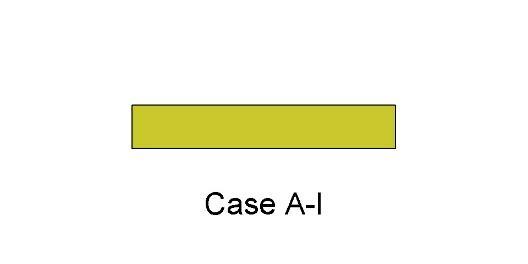
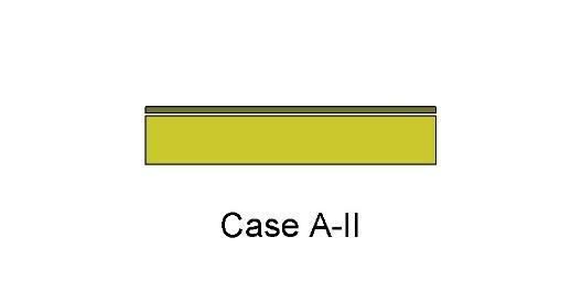
Have you ever thought about building products reducing the carbon dioxide emissions caused by your building? When considered over their useful life, materials like insulation decrease total carbon emissions thanks to their performance benefits. Read on for an explanation of how this can work in your designs.What is Total Carbon?Total carbon captures the idea that the carbon impacts of buildings should be considered holistically across the building's entire life span and sometimes beyond. (In this context, "carbon" is shorthand for carbon dioxide (CO2) emissions.) Put simply, total carbon is calculated by adding a building's embodied carbon to its operational carbon.Total Carbon = Embodied Carbon + Operational CarbonWhat is Embodied Carbon?Embodied carbon is comprised of CO2 emissions from everything other than the operations phase of the building. This includes raw material supply, manufacturing, construction/installation, maintenance and repair, deconstruction/demolition, waste processing/disposal of building materials, and transport between each stage and the next. These embodied carbon phases are indicated by the gray CO2 clouds over the different sections of the life cycle in the image below.We often focus on "cradle-to-gate" embodied carbon because this is the simplest to calculate. "Cradle-to-gate" is the sum of carbon emissions from the energy consumed directly or indirectly to produce the construction materials used in a building. The "cradle to gate" approach neglects the remainder of the embodied carbon captured in the broader "cradle to grave" assessment, a more comprehensive view of a building's embodied carbon footprint.What is Operational Carbon?Operational carbon, on the other hand, is generated by energy used during a building's occupancy stage, by heating, cooling, and lighting systems; equipment and appliances; and other critical functions. This is the red CO2 cloud in the life-cycle graphic. It is larger than the gray CO2 clouds because, in most buildings, operational carbon is the largest contributor to total carbon.What is Carbon Dioxide Equivalent (CO2e)?Often, you will see the term CO2e used. According to the US Environmental Protection Agency (EPA), "CO2e is simply the combination of the pollutants that contribute to climate change adjusted using their global warming potential." In other words, it is a way to translate the effect of pollutants (e.g. methane, nitrous oxide) into the equivalent volume of CO2 that would have the same effect on the atmosphere.Today and the FutureToday, carbon from building operations (72%) is a much larger challenge than that from construction materials' embodied carbon (28%) (Architecture 2030, 2019). Projections into 2050 anticipate the operations/embodied carbon split will be closer to 50/50, but this hinges on building designs and renovations between now and 2050 making progress on improving building operations.Why Insulation?Insulation, and specifically continuous insulation on low-slope roofs, is especially relevant to the carbon discussion because, according to the Embodied Carbon 101: Envelope presentation by the Boston Society for Architecture: Insulation occupies the unique position at the intersection of embodied and operational carbon emissions for a building. Insulation is the only building material that directly offsets operational emissions. It can be said to pay back its embodied carbon debt with avoided emissions during the building's lifetime.A Thought Experiment on Reducing Total CarbonTo make progress on reducing the total carbon impact of buildings, it is best to start with the largest piece of today's pie, operational carbon. Within the range of choices made during building design and construction, not all selections have the same effect on operational carbon.When making decisions about carbon and energy reduction strategies, think about the problem as an "investment" rather than a "discretionary expense." Discretionary expenses are easier to reduce or eliminate by simply consuming less. In the example below, imagine you are flying to visit your client's building. Consider this a "discretionary expense." The input on the far left is a given number of kilograms of carbon dioxide equivalent (CO2e) generated for the flight, from the manufacturing of the airplane, to the fuel it burns, to its maintenance. The output is the flight itself, which creates CO2 emissions, but no durable good. In this case, the only CO2 reduction strategy you can make is to make fewer or shorter flights, perhaps by consolidating visits, employing a local designer of record, or visiting the building virtually whenever possible. Now consider the wallpaper you might specify for your client's building. It involves a discretionary expenditure of CO2e, in this case, used to produce a durable good. However, this durable good is a product without use-phase benefits. In other words, it cannot help to save energy during the operational phase of the building. It has other aesthetic and durability benefits, but no operational benefits to offset the CO2 emissions generated to create it. Your choices here are expanded over the previous example of an airplane flight. You can limit CO2 by choosing a product with a long useful life. You can also apply the three Rs: reduce the quantity of new product used, reuse existing material when possible, and recycle product scraps at installation and the rest at the end of its lifespan. In the final step in our thought experiment, consider the insulation in your client's building. As before, we must generate a certain amount of CO2e to create a durable good. In this case, it's one with use-phase benefits. Insulation can reduce operational energy by reducing heat flow through the building enclosure, reducing the need to burn fuel or use electricity to heat and cool the building. The good news is that, in addition to the other strategies considered for the flight and the wallpaper, here you can also maximize operational carbon savings to offset the initial embodied carbon input. And, unlike the discretionary nature of some flights and the often optional decision to use furnishings like wallpaper, heating and cooling are necessary for the functioning of almost all occupied buildings.Based on this example, you can consider building products with operational benefits, like insulation, as an "investment." It is appropriate to look at improving the building enclosure and understanding what the return on the investment is from a carbon perspective. As the comparison above demonstrates, if you have a limited supply of carbon to "invest", putting it into more roof insulation is a very smart move compared to "spending" it on a discretionary flight or on a product without use-phase carbon benefits, such as wallpaper.This means we should be careful not to measure products like insulation that save CO2e in the building use-phase savings only by their embodied carbon use, but by their total carbon profile. So, how do we calculate this?Putting It to the TestWe were curious to know just how much operational carbon roof insulation could save relative to the initial investment of embodied carbon required to include it in a building. To understand this, we modeled the US Department of Energy's (DOE) Standalone Retail Prototype Building located in Climate Zone 4A to comply with ASHRAE 90.1-2019 energy requirements. We took the insulation product's embodied energy and carbon data from the Polyisocyanurate Insulation Manufacturers Association's (PIMA) industry-wide environmental product declaration (EPD).To significantly reduce operational carbon, the largest carbon challenge facing buildings today, the returns on the investment of our building design strategies need to be consistent over time. This is where passive design strategies like building enclosure improvements really shine. They have much longer service lives than, for example, finish materials, leading to sustained returns.Specifically, we looked here at how our example building's roof insulation impacted both embodied and operational carbon and energy use. To do this, we calculated the cumulative carbon savings over the 75-year life of our model building. In our example, we assumed R-30 insulation installed at the outset, increased every 20 years by R-10, when the roof membrane is periodically replaced.In our analysis, the embodied CO2e associated with installing R-30 (shown by the brown curve in years -1 to 1), the embodied carbon of the additional R-10 of insulation added every 20 years (too small to show up in the graph), and the embodied carbon represented by end-of-life disposal (also too small to show up) are all taken into account. About five months after the building becomes operational, the embodied carbon investment of the roof insulation is dwarfed by the operational savings it provides. The initial and supplemental roof insulation ultimately saves a net of 705 metric tons of carbon over the life of the building.If you want to see more examples like the one above, check out PIMA's study, conducted by the consulting firm ICF. The research group looked at several DOE building prototypes across a range of climate zones, calculating how much carbon, energy, and money can be saved when roof insulation is upgraded from an existing baseline to current code compliance. Their results can be found here. Justin Koscher of PIMA also highlighted these savings, conveniently sorted by climate zone and building type, here.Support for Carbon Investment DecisionsSo how can you make sure you address both operational and embodied carbon when making "carbon investment" decisions? We've prepared a handy chart to help.First, when looking at lower-embodied-carbon substitutions for higher-embodied-carbon building materials or systems (moving from the upper-left red quadrant to the lower-left yellow quadrant in the chart), ensure that the alternatives you are considering have equivalent performance attributes in terms of resilience and longevity. If an alternative material or system has lower initial embodied carbon, but doesn't perform as well or last as long as the specified product, then it may not be a good carbon investment. Another consideration here is whether or not the embodied carbon of the alternative is released as emissions (i.e. as part of its raw material supply or manufacturing, or "cradle to gate" stages), or if it remains in the product throughout its useful life. In other words, can the alternative item be considered a carbon sink? If so, using it may be a good strategy.Next, determine if the alternative product or system can provide operational carbon savings, even if it has high embodied energy (upper-right yellow quadrant). If the alternative has positive operational carbon impacts over a long period, don't sacrifice operational carbon savings for the sake of avoiding an initial embodied product carbon investment when justified for strategic reasons.Last, if a product has high operational carbon savings and relatively low embodied carbon (lower-right green quadrant), include more of this product in your designs. The polyiso roof insulation in our example above fits into this category. You can utilize these carbon savings to offset the carbon use in other areas of the design, like aesthetic finishes, where the decision to use the product may be discretionary but desired.When designing buildings, we need to consider the whole picture, looking at building products' embodied carbon as a potential investment yielding improved operational and performance outcomes. Our design choices and product selection can have a significant impact on total carbon targets for the buildings we envision, build, and operate.Click these links to learn more about GAF's and Siplast's insulation solutions. Please also visit our design professional and architect resources page for guide specifications, details, innovative green building materials, continuing education, and expert guidance.We presented the findings in this blog in a presentation called "Carbon and Energy Impacts of Roof Insulation: The Whole[-Life] Story" given at the BEST6 Conference on March 19, 2024 in Austin, Texas.References:Architecture 2030. (2019). New Buildings: Embodied Carbon. https://web.archive.org/web/20190801031738/https://architecture2030.org/new-buildings-embodied/ Carbon Leadership Forum. (2023, April 2). 1 - Embodied Carbon 101. https://carbonleadershipforum.org/embodied-carbon-101/
By Authors Elizabeth Grant
September 18, 2024

